Quickly create Data-flow Diagrams for Systems and Processes
Data-flow diagrams (DFD) are useful to represent the way data flows between entities, data stores and processes in a system (or process).
DFD's show the inputs and outputs and give a high-level view that is useful for the planning stage of a system or process. Here the focus is not on control or sequence of activities (flowcharts and sequence diagrams are recommended for that).
For any given process you can have multiple Data-flow diagrams, one high level (called context-diagram), and multiple DFD's for internal processes when you need more detailed inputs and outputs.
Diagram.codes engine makes it easy to create and share your data-flow diagrams. The text convention is intuitive and simple to use:
Example data-flow diagram #

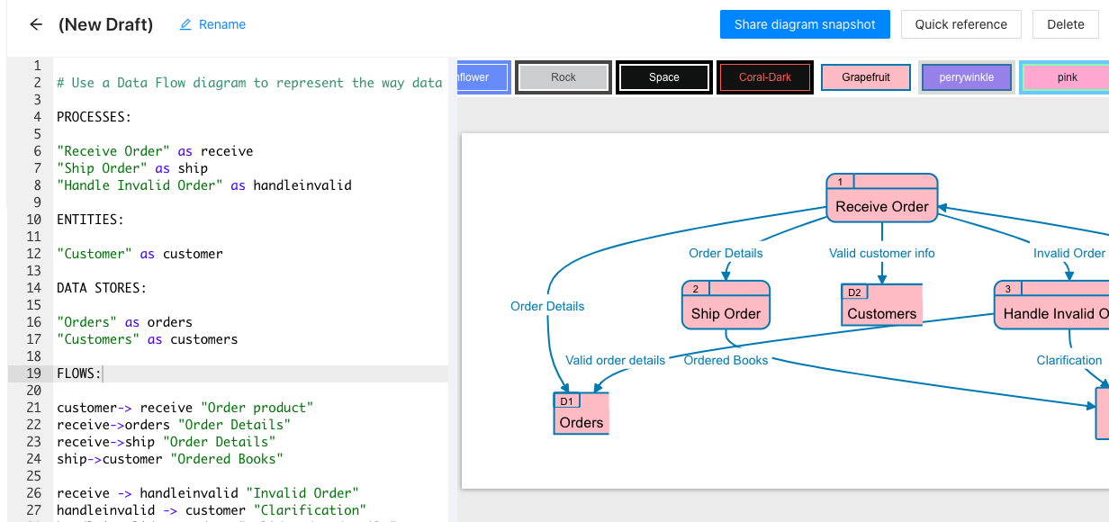
Diagram.codes uses an intuitive text description to automatically generate the diagram:
PROCESSES:

"Receive Order" as receive
"Ship Order" as ship
"Handle Invalid Order" as handleinvalid

ENTITIES:

"Customer" as customer

DATA STORES:

"Orders" as orders
"Customers" as customers

FLOWS:

customer -> receive "Order product"
receive -> orders "Order Details"
receive -> ship "Order Details"
ship -> customer "Ordered Books"

receive -> handleinvalid "Invalid Order"
handleinvalid -> customer "Clarification"
handleinvalid -> orders "Valid order details"
receive->customers "Valid customer info"
rece
Data-flow diagram symbols #
External Entity #
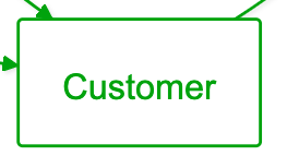
An actor that interacts with your system/process, provides inputs and can receive output from a process
Process #
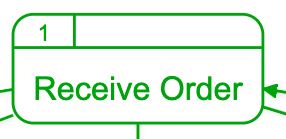
Is the activity that receives an input and generates an output that can be stored or communicated to an entity.
Data Store #
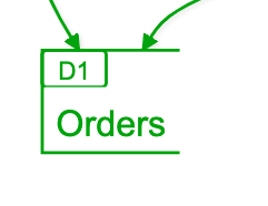
A data repository like a database.
Data Flow #
Represented by an arrow, it shows the flow of data between two elements.
If you want to know more about the text-to-diagram features of diagram.codes please visit our product website.